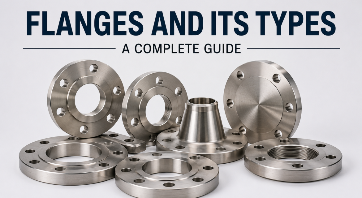
What is a Flange?
A flange is a flat, disc-shaped mechanical component used to connect pipes, valves, pumps, and other equipment in industrial piping systems. Flanges are bolted together with a gasket placed between their mating faces, creating a secure, leak-proof seal that can be easily assembled, disassembled, inspected, and maintained.
Flanges are found in almost every industry that moves fluids or gases, from oil refineries and power plants to water treatment facilities and pharmaceutical factories. Without flanges, modern piping infrastructure as we know it would not exist.
The global flanges market was valued at $6.4 billion in 2025 and is expected to grow to $11.2 billion by 2035, at a CAGR of 5.8%, driven by expanding energy infrastructure, chemical processing, and water management sectors.
Flanges have been in use since the late 18th century, evolving from simple flat rings into highly engineered components manufactured to precise international standards. Today, a single large refinery or power plant may use tens of thousands of flanges across its piping network, each one critical to the integrity of the system.
The word “flange” itself comes from the Old French word “flangir,” meaning to bend or turn outward. In engineering terms, it refers to an external or internal ridge or rim that provides strength, guides motion, or allows attachment to another object.
How Does a Flange Work?
A flange works by transferring the internal pressure of a pipe into bolt tension, which compresses a gasket between two mating flange faces to form a seal. The basic components of a flanged joint are:
- The Flange — the disc-shaped connector
- The Gasket — the sealing element placed between two flanges
- The Bolts and Nuts — fasteners that pull the two flanges together
- The Pipe or Equipment — what the flange is attached to
When bolts are tightened, they compress the gasket uniformly, filling any microscopic surface imperfections and preventing leaks. Proper bolt torque and gasket selection are critical to achieving a reliable seal.
The entire flanged joint system is a balance between three forces: the bolt load applied during assembly, the hydrostatic end force created by internal fluid pressure, and the seating stress required to keep the gasket compressed and leak-free during operation. Engineers must account for all three when designing a flanged connection, especially in high-pressure and high-temperature service.
Surface finish also plays a key role. Flange faces are machined to specific roughness values, typically 125 to 250 micro-inches AARH (Average Arithmetic Roughness Height) for raised face flanges, to ensure proper gasket seating without damaging softer gasket materials.
Types of Flanges: A Complete Guide
There are many types of flanges used across industries. Each type is designed for specific pressure ratings, temperatures, pipe sizes, and installation conditions. Here is a comprehensive breakdown:
1. Weld Neck Flange (WNF)
Most popular for high-pressure applications
A weld neck flange features a long, tapered neck that gradually narrows to match the pipe wall thickness. It connects to the pipe through butt welding, ensuring an even distribution of stress at the weld joint and reducing pressure concentration.
Key Features:
- Long tapered hub provides superior stress distribution
- Ideal for high-pressure and high-temperature service
- Radiographic (X-ray) inspection of the weld is possible
- Available in all pressure classes from 150 to 2500
Applications: Oil and gas pipelines, refineries, chemical plants, steam lines, cryogenic service
Materials: Carbon steel (ASME SA-105), stainless steel (SA-182 F304/316), chrome-moly grades (F11, F22, F91)
The weld neck flange is the preferred choice wherever integrity cannot be compromised. Its gradual bore transition eliminates turbulence and erosion at the connection point, making it ideal for slurries, abrasive fluids, and high-velocity gas flows. It is the only flange type that allows full radiographic weld inspection, which is mandatory in many critical process and nuclear applications.
2. Slip-On Flange (SOF)
Best for low to medium pressure, easy installation
A slip-on flange is a ring (with or without a hub) that slides over the outside of the pipe and is then welded in place, both on the inside and outside, for added strength. It is easier to align than a weld neck flange and costs less.
Key Features:
- Slides over the pipe for easy positioning
- Requires two fillet welds (inside and outside)
- Lower cost than weld neck flanges
- Suitable for lower-pressure applications
Applications: Water supply systems, low-pressure steam, fire protection systems, general industrial piping
Materials: Carbon steel, stainless steel, alloy steel
Slip-on flanges are approximately 20 to 30 percent cheaper than weld neck flanges of the same size and rating. Their ease of installation makes them popular for large-scale utility projects where thousands of connections must be made quickly. However, they are not recommended for cyclic service, sub-zero temperatures, or flammable fluid applications where weld integrity is critical.
3. Blind Flange
Used to terminate or isolate piping systems
A blind flange is a solid disc with no bore, used to seal the end of a pipe, nozzle, or vessel opening. Despite having no opening, blind flanges must withstand full line pressure and are among the most mechanically stressed flange types.
Key Features:
- Completely seals the end of a pipe or opening
- Easy to remove for future access or inspection
- Must withstand full pressure from one side
- Available in all pressure ratings
Applications: Pipe end closures, vessel nozzle blanking, pressure testing, future pipe extensions
Materials: Carbon steel, stainless steel, duplex stainless, exotic alloys
Blind flanges are also widely used during hydrostatic pressure testing of piping systems. A temporary blind flange is installed at the pipe end, the system is pressurized with water, and inspectors check for leaks across all joints. After testing, the blind is removed and replaced with the permanent connection. In process plants, permanent blind flanges are installed on standby nozzles intended for future expansion.
4. Socket Weld Flange (SWF)
Designed for small-diameter, high-pressure piping
A socket weld flange has a socket-type recess into which the pipe is inserted before being fillet welded. The pipe fits snugly inside the socket, providing good strength and a clean external finish.
Key Features:
- Pipe is inserted into a counter-bore socket
- Single fillet weld on the outside
- Better flow characteristics than threaded flanges
- Preferred for small bore piping (NPS 2 and below)
Applications: Hydraulic systems, high-pressure steam, chemical injection lines, instrumentation piping
Materials: Carbon steel, stainless steel, alloy steel
One important installation note for socket weld flanges: the pipe must be inserted fully into the socket and then pulled back approximately 1.5mm before welding. This gap prevents the pipe from butting against the bottom of the socket during thermal expansion, which would crack the weld. This detail is often missed by inexperienced installers and is a common cause of socket weld failures in service.
5. Threaded Flange (Screwed Flange)
No welding required, ideal for hazardous or explosive environments
A threaded flange has internal (female) threads that match the external threads on the pipe. The pipe simply screws into the flange, requiring no welding. This makes it suitable for locations where welding is prohibited due to explosion hazards.
Key Features:
- No welding required
- Quick and simple installation
- Not suitable for high pressure or temperature cycling
- Risk of leakage at threads over time
Applications: Flammable gas lines, low-pressure water and air systems, remote locations without welding equipment
Materials: Carbon steel, stainless steel, brass, PVC (non-metallic)
Threaded flanges are not suitable for services involving temperature cycling or vibration because repeated thermal expansion and contraction can loosen the threaded connection over time, leading to leaks. In such cases, a seal weld is sometimes added after threading to lock the connection, though this eliminates the no-welding advantage and makes future dismantling more difficult.
6. Lap Joint Flange
Used with stub ends for systems that require frequent dismantling
A lap joint flange consists of two components: the lap joint flange itself and a stub end (also called a lap joint stub end). The flange is not welded to the pipe directly. Instead, it slides freely over the pipe and mates with the back of the stub end. This allows the flange to rotate freely, making bolt hole alignment very easy.
Key Features:
- Flange slides over the pipe and rotates freely
- Requires a stub end welded to the pipe
- Bolt holes can be aligned easily due to free rotation
- Cost-effective when using expensive alloys (only the stub end needs to be alloy)
Applications: Systems that require frequent dismantling for cleaning or inspection, cryogenic piping, corrosive service
Materials: Carbon steel flange with stainless steel or exotic alloy stub end (cost optimization)
The lap joint flange offers a significant cost advantage in exotic alloy applications. Since only the stub end (the part that contacts the fluid) needs to be made from expensive alloy material, while the backing flange (which only handles bolt loads) can be made from low-cost carbon steel, overall material costs can be reduced by 40 to 60 percent in high-alloy piping systems.
7. Long Weld Neck Flange (LWN)
Extended version of the weld neck flange for special applications
A long weld neck flange is similar to a standard weld neck but has a much longer neck that acts as a nozzle extension. It is commonly used in pressure vessels, heat exchangers, and columns where the flange must connect directly to the vessel shell.
Key Features:
- Extended neck acts as a nozzle or pipe section
- Stronger connection to vessels and heat exchangers
- Withstands high pressure and temperature
- Common in petroleum refining and gas processing
Applications: Oil and gas refineries, heat exchangers, reactors, distillation columns
Long weld neck flanges are designed to be welded directly to a vessel shell or head, eliminating the need for a separate nozzle pipe. The elongated neck also allows for insulation of the vessel wall without interference with the flange bolting. They are manufactured to tighter tolerances than standard weld neck flanges because they serve as an integral part of pressure vessel construction.
8. Orifice Flange
Specialized for flow measurement
Orifice flanges are used in pairs and have radial tapped holes in the flange body to allow the connection of pressure differential measurement instruments. They are used with orifice plates to measure the flow rate of fluids and gases in a pipeline.
Key Features:
- Has radial pressure taps on both flanges
- Used in conjunction with an orifice plate
- Measures differential pressure to calculate flow rate
- Precision machined for accurate measurement
Applications: Flow measurement in oil and gas pipelines, refineries, chemical plants, custody transfer metering
Orifice flanges come as a matched set. The upstream and downstream flanges are precision-machined together to ensure the pressure taps are perfectly aligned and the orifice plate sits square to the flow direction. The accuracy of flow measurement depends heavily on the quality of the flange machining and the correct installation of the orifice plate with the beveled edge facing downstream.
9. Reducing Flange
Connects pipes of two different diameters
A reducing flange allows the connection of two pipes of different nominal diameters, eliminating the need for a separate reducer fitting. The flange has one bore size but the outer dimensions of a larger flange.
Key Features:
- Eliminates the need for a separate reducer
- Cost-effective and space-saving
- Available in various size combinations
Applications: Pump connections, equipment nozzles, wherever two different pipe sizes must be joined
Reducing flanges save both cost and installation space by combining the function of a flange and a reducer into a single forged component. They are particularly useful at pump suction and discharge nozzles where the pipe size frequently differs from the pump port size.
10. Expander Flange
Increases pipe bore at the flange connection
An expander flange (also called a reducing weld neck flange) is used when the pipe size needs to increase at the point of connection, for example at the discharge of a pump where the pipe diameter steps up.
Applications: Pump discharge connections, compressor inlet/outlet, expansion points in process piping
Expander flanges eliminate the need for a concentric reducer fitting at pump or compressor discharge connections. This reduces the number of welds, shortens the overall piping spool length, and simplifies the installation. In compact skid-mounted systems where space is limited, expander flanges are a practical engineering solution.
11. Spectacle Blind Flange (Figure 8 Blind)
Used for positive isolation in maintenance situations
A spectacle blind (also called a figure-8 blind) is a combination of a blind disc and a spacer ring joined together, shaped like a pair of spectacles or the figure 8. It is installed permanently between two flanges and can be rotated to either isolate (blind position) or allow flow (open position).
Key Features:
- Permanent installation between two flanges
- Quickly switches between isolated and open position
- Provides visual confirmation of isolation status
- No need to remove and reinstall a separate blind
Applications: Plant shutdown isolation, maintenance isolation, hazardous fluid line isolation, pressure vessel isolation
Spectacle blinds are a safety-critical component in process plants. During plant turnarounds and maintenance shutdowns, they provide positive, visible isolation of equipment from pressurized lines, something that a closed valve alone cannot guarantee. They are required by many safety regulations in the oil, gas, and chemical industries as a mandatory isolation method.
12. Paddle Blind and Spacer
Removable isolation device used between existing flanges
A paddle blind is a single solid disc (without the spacer ring) that is inserted between two flanges to provide temporary isolation. A paddle spacer (or ring spacer) is the open-ring equivalent that replaces the blind when the line is returned to service.
Key Features:
- Temporary isolation solution
- Used in pairs with paddle spacers
- Available in various pressure ratings and sizes
- Color-coded for quick identification (red for blind, green for spacer)
Applications: Temporary line isolation during maintenance, pre-commissioning, turnaround activities
Flange Face Types
Beyond the flange type itself, the face (the mating surface) is equally important for achieving a reliable seal:
Raised Face (RF): The most common face type. A raised circular surface concentrates bolt load on the gasket. Used for medium to high pressure. The raised face height is 1/16 inch for Class 150 and 300, and 1/4 inch for Class 600 and above.
Flat Face (FF): The entire flange face is flat. Used with cast iron flanges and where the mating equipment has a flat face (pumps, valves). Full-face gaskets are used with flat face flanges to prevent the gasket from being pinched at the bore.
Ring Type Joint (RTJ): A precision-machined groove holds a metallic ring gasket. Provides the highest integrity seal for extreme pressure and temperature. RTJ ring gaskets are softer than the flange material so they deform to fill the groove, creating a metal-to-metal seal.
Tongue and Groove (T&G): One flange has a raised ring (tongue) and the mating flange has a matching groove. Self-aligning and provides an excellent seal. Widely used in heat exchanger covers and valve bonnets.
Male and Female (MF): Similar to T&G but shallower profile. Common in heat exchanger applications. The female flange has a recessed area and the male flange has a matching raised area.
Lap Joint Face: Used specifically with lap joint flanges. The stub end provides the sealing face. Not used with gaskets in the traditional sense. Sealing occurs at the stub end face.
Flange Materials: Which One to Choose?
| Material | Standard | Best For |
|---|---|---|
| Carbon Steel | ASME SA-105 | General service, cost-effective |
| Stainless Steel 304/316 | ASME SA-182 | Corrosive environments, food grade |
| Chrome-Moly F11/F22/F91 | ASME SA-182 | High temperature steam lines |
| Duplex Stainless 2205/2507 | ASME SA-182 | Offshore, chloride-rich environments |
| Nickel Alloy (Inconel, Hastelloy) | ASME SA-182 | Extreme corrosion, cryogenic |
| Alloy 625 / Alloy 825 | ASME SB-564 | Chemical processing, seawater |
| Cast Iron / Ductile Iron | ASME A126 | Water utilities, low-pressure |
| Titanium | ASME SB-381 | Highly corrosive, lightweight applications |
| Copper-Nickel (70/30) | ASME SB-151 | Marine and seawater piping systems |
Carbon steel holds the largest share of the flange market due to its cost-efficiency, strength, and versatility. Stainless steel and nickel alloys dominate pharmaceutical, offshore, and chemical sectors. When selecting flange material, engineers must also consider the compatibility of the gasket, bolting material, and pipe material to avoid galvanic corrosion at dissimilar metal interfaces.
Gasket Types Used with Flanges
Gaskets are as important as the flanges themselves. Choosing the wrong gasket is one of the most common causes of flanged joint leakage.
Full Face Gasket: Covers the entire flange face including bolt holes. Used exclusively with flat face flanges on cast iron and non-metallic equipment.
Ring Gasket: Fits inside the bolt circle, covering only the raised face area. The most common gasket type for raised face flanges.
Spiral Wound Gasket (SWG): Made from alternating layers of metallic strip and soft filler material (graphite or PTFE). The industry standard for medium to high pressure and temperature service. Available with inner and outer rings for additional stability.
Kammprofile Gasket: A solid metal core with concentric grooves, covered with a soft sealing layer. Provides high reliability in demanding service conditions.
Ring Type Joint Gasket (RTJ): Solid metallic ring (oval or octagonal cross-section) used in RTJ flanges. Provides a metal-to-metal seal under high bolt load.
PTFE Gasket: Non-metallic, chemically resistant gasket used in pharmaceutical, food, and aggressive chemical service where metal contamination is not acceptable.
ASME / ANSI Flange Pressure Classes
Flanges are rated by pressure class, which determines the maximum allowable pressure at various temperatures:
- Class 150 — Low pressure, general service
- Class 300 — Medium pressure
- Class 600 — Medium-high pressure
- Class 900 — High pressure
- Class 1500 — Very high pressure
- Class 2500 — Extreme pressure (highest standard class)
Pressure class selection depends on the operating pressure, temperature, and material of the flange. Higher temperature reduces the allowable pressure for the same class. For example, a Class 300 carbon steel (A105) flange rated at 740 PSI at 100°F is only rated at 500 PSI at 500°F. Engineers must always consult the appropriate ASME B16.5 pressure-temperature table for the exact rating at operating conditions.
Flange Bolting: Studs, Bolts, and Nuts
Flanges are only as reliable as their bolting. The wrong bolt material or incorrect torque is a leading cause of flange leaks.
Stud Bolts with Hex Nuts: The standard for most industrial flanges. Full-length threaded studs with a nut on each end provide uniform clamping force.
Machine Bolts (Hex Head Bolts): Used in Class 150 and 300 flanges in non-critical service. Less preferred than stud bolts for high-integrity applications.
Common Bolting Materials:
| Bolt Material | Nut Material | Service |
|---|---|---|
| ASTM A193 B7 | A194 2H | General service up to 450°C |
| ASTM A193 B8 (SS 304) | A194 8 | Cryogenic and corrosive |
| ASTM A193 B7M | A194 2HM | Sour service (H2S) per NACE MR0175 |
| ASTM A320 L7 | A194 7 | Low temperature service |
All bolts should be lubricated before installation to ensure that applied torque accurately translates to bolt load (clamping force). Never torque dry bolts. Friction variation can cause up to 50 percent difference in actual bolt load for the same applied torque.
Key International Standards for Flanges
- ASME B16.5 — Pipe flanges and flanged fittings (NPS 1/2 to 24)
- ASME B16.47 — Large diameter steel flanges (NPS 26 to 60)
- ASME B16.36 — Orifice flanges
- ASME B16.48 — Line blanks (spectacle blinds and paddle blinds)
- DIN 2501 — German standard flanges (widely used in Europe)
- EN 1092 — European standard flanges
- BS 4504 — British standard (now superseded by EN 1092)
- JIS B2220 — Japanese Industrial Standard flanges
- API 6A — Flanges for wellhead and Christmas tree equipment (oil and gas)
- API 6B — Flanges for pipeline valves, fittings, and wellhead equipment
- MSS SP-44 — Steel pipeline flanges (large bore, high-pressure)
- AWWA C207 — Steel pipe flanges for waterworks service
Industry Applications of Flanges
Oil and Gas: Weld neck and blind flanges dominate upstream and downstream pipelines. RTJ face flanges are standard for high-pressure wellhead connections. Long weld neck flanges are critical in refinery columns. Spectacle blinds are mandatory at all equipment isolation points. The 12 to 24 inch size segment is one of the fastest growing in this sector.
Chemical and Petrochemical Processing: Corrosion-resistant stainless steel and exotic alloy flanges (Hastelloy, Inconel) handle aggressive chemicals. Lap joint flanges simplify maintenance in units that require frequent cleaning. Orifice flanges are used extensively for custody transfer metering of feedstocks and products.
Power Generation: High-temperature chrome-moly flanges are essential in steam turbine and boiler piping. Class 900 and 1500 flanges are common in main steam lines. Nuclear power plants require flanges manufactured to the strictest quality standards, including NDE, material traceability, and third-party inspection.
Water and Wastewater Treatment: Ductile iron and carbon steel slip-on flanges are standard. ASME B16.47 covers the large-diameter flanges used in water mains. AWWA C207 flanges are specifically designed for waterworks service with drilling patterns compatible with water utility equipment.
Pharmaceutical and Food and Beverage: Stainless steel 316L flanges with polished (sanitary) surfaces meet hygiene requirements. Tri-clamp or sanitary flanges are specific to this sector. All surfaces must meet Ra (roughness) values below 0.8 microns to prevent bacterial growth in product-contact piping.
Mining and Metals: Abrasion-resistant alloy flanges handle slurry and high-wear applications. Large-diameter flanges are used in ore processing, tailings management, and mine dewatering systems.
LNG and Cryogenic Applications: Cryogenic service requires flanges made from materials that retain toughness at extremely low temperatures (down to -196°C for LNG). Austenitic stainless steel and nickel alloys are the materials of choice. Lap joint flanges are preferred in cryogenic piping because the free-rotating flange accommodates thermal contraction during cooldown without inducing stress into the pipe.
Shipbuilding and Marine: Marine flanges must resist saltwater corrosion. Copper-nickel (70/30 and 90/10) and duplex stainless steel flanges are commonly used in seawater cooling systems and ballast piping. Marine flanges follow classification society standards (Lloyd’s Register, DNV-GL, ABS).
How to Select the Right Flange: A Buyer’s Checklist
Before purchasing or specifying a flange, engineers and procurement teams should confirm:
- Operating pressure and temperature — Determines pressure class (150 to 2500)
- Pipe size and schedule — Determines bore and dimensions
- Fluid or gas type — Determines material (carbon steel, stainless, alloy)
- Corrosion environment — Offshore, chemical, saline? Consider duplex or nickel alloy
- Welding availability — If welding is restricted, use threaded flanges
- Frequency of dismantling — High dismantling frequency = lap joint flange
- Flow measurement needed — Specify orifice flanges
- Applicable standard — ASME, DIN, EN, JIS, API depending on project location
- Gasket type — Soft gasket (RF/FF), semi-metallic (spiral wound), metallic ring (RTJ)
- Third-party inspection requirements — Impacts documentation, material certs, NDE
- Sour service (H2S) — Requires NACE MR0175 compliant materials and hardness limits
- Fire safe requirements — Some applications require flanges and gaskets tested to API 607 or API 6FA fire safe standards
Flange Manufacturing Processes
Forging: The most common and preferred manufacturing method. The flange is forged from a solid billet of metal under high pressure, producing a dense, grain-refined microstructure with superior mechanical properties. Forged flanges have higher strength and toughness than cast flanges of the same size.
Casting: Molten metal is poured into a mold and solidified into the flange shape. Casting is used for large-diameter, complex-shaped flanges and for cast iron flanges in low-pressure utility service. Cast flanges may contain internal porosity and are generally not used in critical pressure service.
Fabricated (Plate Flanges): Cut and machined from flat plate. Used for large-diameter, non-standard flanges when forged blanks are unavailable. Plate flanges are used in waterworks and low-pressure applications but are not permitted under some pressure vessel codes.
Rolled Ring Forging: A specialized forging process where a round billet is pierced and then rolled in a ring-rolling mill to produce a seamless ring. This process produces flanges with a continuous grain flow around the circumference, giving superior fatigue resistance. Most standard industrial flanges are manufactured by this process.
Flange Inspection and Testing Methods
Visual Inspection (VT): The most basic inspection. The flange face, bore, hub, and surface finish are visually examined for cracks, pits, gouges, and surface defects.
Dimensional Inspection: The flange is measured against the applicable standard (ASME B16.5, B16.47, etc.) to verify all critical dimensions: outer diameter, bore, bolt circle diameter, bolt hole size and location, flange face diameter, thickness, and hub dimensions.
Liquid Penetrant Testing (LPT/PT): A liquid dye is applied to the flange surface, penetrates surface-breaking cracks and defects, and is revealed by a developer. Used to detect surface cracks on non-magnetic materials.
Magnetic Particle Testing (MPT/MT): Used only on ferromagnetic materials (carbon steel, low alloy steel). A magnetic field is applied, and iron particles reveal surface and near-surface defects. Faster and more sensitive than liquid penetrant for suitable materials.
Ultrasonic Testing (UT): High-frequency sound waves are sent through the flange to detect internal defects such as inclusions, laminations, and internal cracks. Also used for wall thickness measurement.
Positive Material Identification (PMI): X-ray fluorescence (XRF) or optical emission spectrometry (OES) verifies that the flange is made from the correct alloy. Essential for stainless steel, chrome-moly, and exotic alloy flanges where mixing materials with similar appearances can have catastrophic consequences.
Hardness Testing: Verifies that the flange material meets the hardness limits required for sour service (NACE MR0175/ISO 15156) or other special service conditions.
Hydrostatic Testing: The assembled flanged piping system is pressurized with water to 1.5 times the design pressure and held for a specified period to verify the integrity of all flanged joints.
Flange Maintenance and Inspection Best Practices
Flanged joints, if poorly maintained, are a major source of process leaks. Follow these practices:
- Re-torque flanges after the first heat cycle in hot service to account for gasket relaxation
- Inspect gaskets at every shutdown and never reuse a compressed gasket
- Check for corrosion at the flange face and bolt holes, especially in offshore environments
- Use proper bolt lubricant to achieve accurate bolt load from torque values
- Document bolt torque records for safety-critical flanges
- Conduct PMI (Positive Material Identification) to verify correct material in critical service
- Apply protective coatings on carbon steel flanges in corrosive environments
- Replace flange face gaskets whenever a flanged joint is opened, regardless of the gasket’s apparent condition
- Check flange face finish before reassembly. A damaged or corroded face cannot be adequately sealed even with a new gasket
- Use torque wrenches and never impact wrenches for safety-critical bolted flange joints
Common Causes of Flanged Joint Failures
Understanding why flanged joints fail is as important as knowing how to install them correctly.
Improper Bolt Torque: Under-torqued bolts result in insufficient gasket compression and leakage. Over-torqued bolts can crush soft gaskets, crack brittle flanges, or yield the bolts themselves, all leading to leakage.
Wrong Gasket Selection: Using a gasket rated for lower pressure or temperature than the actual service conditions is a guaranteed path to failure. Compatibility of the gasket with the fluid must also be verified.
Flange Face Damage: Scratches, pits, or corrosion on the flange face create leak paths that even a perfect gasket cannot seal. Flange faces must be inspected and reconditioned or replaced before reassembly.
Misalignment: Forcing flanges together that are not naturally aligned puts bending stress on the pipe, can crack welds, and prevents uniform gasket compression. Flanges that require more than finger-tight bolt engagement to close the gap should be realigned by a piping engineer.
Material Mix-Up: Installing a carbon steel flange in a stainless steel corrosive service line, or a Class 150 flange where Class 600 is required, can lead to immediate or rapid failure. PMI testing prevents this.
Thermal Cycling: Repeated heating and cooling cycles can relax bolt load over time through a phenomenon called creep relaxation, especially in high-temperature service. Scheduled re-torquing programs are essential in such systems.
Vibration: Piping systems subject to mechanical vibration (pump discharge, compressor lines, rotating equipment connections) can experience bolt loosening over time. Locking devices, lock wire, or Nord-Lock washers are used to prevent vibration-induced loosening.
Environmental and Safety Considerations
Fugitive Emissions: Flanged joints in gas service are a source of fugitive volatile organic compound (VOC) emissions in process plants. Many countries now require low-emission or low-E flanged joints that meet EPA Method 21 or European EN 15848 leakage standards. Spiral wound gaskets with graphite filler are commonly specified for low-emission applications.
Fire Safety: In hydrocarbon processing facilities, flanged joints are designed and installed to minimize the risk of flange leaks igniting fires. Fire-safe gasket materials (graphite, expanded PTFE, metallic) are specified, and flanges in high-consequence locations are shielded with fire-resistant wrapping or spray-applied fireproofing.
Asbestos-Free Requirements: Until the 1980s, many gaskets were made from asbestos-containing materials. All modern industrial plants are now required to use asbestos-free gaskets. Compressed non-asbestos fiber (CNAF) and spiral wound graphite gaskets are the standard replacements.
Corrosion Under Insulation (CUI): Insulated flanges are vulnerable to corrosion caused by water ingress under the insulation. Regular inspection using pulsed eddy current (PEC) or other non-intrusive techniques is required for insulated flanges in outdoor environments.
Conclusion
Flanges are the backbone of every industrial piping system. Selecting the right flange type, material, pressure class, and face type is not just an engineering decision. It is a safety-critical choice that affects plant reliability, maintenance cost, and operational uptime.
The global demand for flanges continues to grow, driven by energy infrastructure expansion, chemical plant construction, and the global push for water management upgrades. With a projected market size of $11.2 billion by 2035, flanges remain one of the most essential components in industrial engineering.
Whether you are an engineer specifying flanges for a new plant, a procurement manager sourcing components, or a supplier looking to educate your customers, this guide gives you the foundation to make confident, informed decisions.
Understanding flange types, materials, standards, and failure modes separates good engineering from great engineering. In an industry where a single leaking flange can shut down an entire plant, cause environmental damage, or endanger lives, getting every flanged joint right is not optional. It is a professional and moral responsibility.